Laboratorio Fly-By-Wire
The activities carried out in the Fly-By-Wire Laboratory essentially deal with the theretical and experimental study of onboard systems and equipments, with special focus on:
- Safety-critical mechatronic systems (flight control actuators, electric motors for aeronautical propulsion)
- Lithium-Ion batteries for UAV applications
- Thrust and lift propellers for UAV applications
The studies are conducted by integrating
- Dynamic modelling/simulation
- Stability assessment and perfomance analysis
- Fault simulations
- Control design and health-monitoring
- Controllability and observability
- Development of health-monitoring algorithms
- Development of finite-state-machines for failure management
- Implementation of control SW on microcontrollers
- Experimental characterization of performances
- Commands tracking and disturbance rejection
- Performance sensitivity to temperature and humidity
- Real-Time Model-/Processor-/Hardware-In-The-Loop (MIL, PIL, HIL) simulations

To conduct the above-mentioned studies, the following facilities are available:
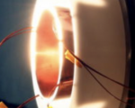
Test rig for electric motors (max 2 kW) and propellers (max diameter 40 cm)
3D resin printer (Elegoo Jupiter SE)
- Net volume: 275 x 150 x 300 mm³
- Screen: 12,8'', LCD 6K
- Resolution: 51um
Climatic chamber (Angelantoni Challenge 250C)
- Net volume: 224 litri
- Operative range of temperature (empty): from -60 °C to +180 °C
- Operative range of relative humidity (empty): from 10 % to 98 %
- Max temperature rate (empty): +/-5 °C/min
- Power draw: max 9 kW ; mean 5.7 kW
Le attività condotte nel Laboratorio Fly-By-Wire riguardano essenzialmente lo studio teorico e sperimentale di impianti e sistemi imbarcati su velivoli, con particolare riferimento a:
- Sistemi meccatronici safety-critical (attuazione comandi di volo, motori elettrici di propulsione)
- Batterie a ioni di litio per applicazioni UAV
- Eliche di spinta e di sostentamento per applicazioni UAV
Gli studi condotti prevedono un'articolazione organica di attività come
- Modellazione/simulazione dinamica
- Stabilità e analisi prestazioni
- Simulazione guasti
- Sviluppo leggi di controllo
- Controllabilità e osservabilità
- Sviluppo algoritmi di monitoraggio
- Sviluppo macchine a stati per gestione avarie
- Implementazione di SW di controllo su microcontrollori
- Sviluppo algoritmi di monitoraggio
- Test di caratterizzazione prestazioni
- Tracciamento comandi e reiezione disturbi
- Sensibilità prestazioni a temperatura e umidità
- Simulazioni Real-Time Model-/Processor-/Hardware-In-The-Loop (MIL, PIL, HIL)
Per lo svolgimento delle attività, presso il Laboratorio FLy-By-Wire sono disponibili le seguenti attrezzature:
Banco prova per motori elettrici (max 2 kW) ed eliche (diametro max 40 cm)
Stampante 3D a resina (Elegoo Jupiter SE)
- Volume utile: 275 x 150 x 300 mm³
- Schermo: 12,8'', LCD 6K
- Risoluzione: 51um
Camera climatica (Angelantoni Challenge 250C)
- Volume utile: 224 litri
- Intervallo operativo di temperatura (a vuoto): da -60 °C a +180 °C
- Intervallo operativo di umidità relativa (a vuoto): da 10 % a 98 %
- Rateo massimo di temperatura (a vuoto): +/-5 °C/min
- Potenza assorbita: max 9 kW ; media 5.7 kW